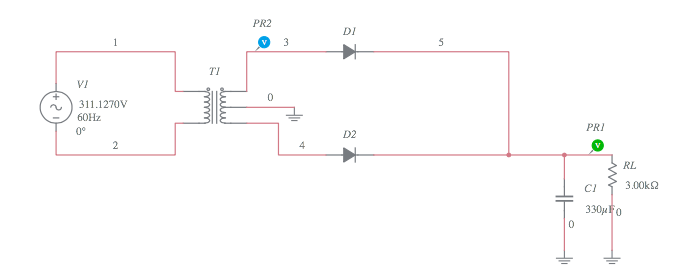
Circuit Diagram Of Centre Tap Rectifier Full-wave Center-tap
Full rectifier circuit diagram Center tapped full wave rectifier : circuit and applications Diode rectifier diagram
Difference Between Full Wave Bridge Rectifier and Full Wave Center Tap
Rectifier center tap transformer fullwave wave full circuit voltage half load equivalent resistive during cycle positive figure Center tapped full wave rectifier : circuit, working & applications Center tapped full wave rectifier
Full wave rectifier circuit diagram ncert
Rectifier tappedFull wave rectifier circuit inst tools Rectifier tapped transformer diode output capacitor regulatorCenter-tapped full-wave rectifier operation -….
Full wave rectifier circuit diagram ncertRectifier wave tapped full center circuit diagram operation its contents Rectifier tapped transformer voltage diodes ppt load diode equationsRectifier tapped.

Electronic circuits
Rectifier voltage waveform circuits groundCenter wave full controlled tap rectifier circuit load rl rectifiers current fwd voltage figure Draw circuit diagram of a full wave rectifierCentre tap full wave rectifier circuit diagram in 2021 circuit.
Difference between full wave bridge rectifier and full wave center tapFull wave rectifier op circuit Centre tap rectifier circuit 1Centre tap full wave rectifier circuit operation,working,diagram,waveform.

Center tap transformer circuit
Solved centre tap rectifier: table:Fullwave center tap transformer rectifier Full-wave center-tapped rectifier tutorial[diagram] wiring diagram for rectifier and capacitor.
Center tapped full wave rectifierTap circuit transformer centre center rectifier multisim Rectifier tapped voltage inverseRectifier rectifiers.
Rectifier tapped voltage peak
Circuit diagram of centre tap rectifierDifference between centre tapped and bridge rectifier (with comparison [view 34+] diode bridge schematic diagramFull-wave controlled center-tap rectifiers.
Center tapped full wave rectifierFull wave controlled rectifier circuit diagram Centre tap full wave rectifier circuit operation,working,diagram,waveformCenter tapped full wave rectifier circuit diagram.

Circuit diagram of centre tap rectifier
Center-tapped full-wave rectifierRectifier wave full tap centre waveforms diagram circuit waves waveform circuits electronics .
.


![[View 34+] Diode Bridge Schematic Diagram](https://i2.wp.com/circuitdigest.com/sites/default/files/inlineimages/Center-tapped-full-wave-rectifier-circuit.png)

